Cepstral analysis
The technique of cepstral analysis is fairly well described in Wakita's papers
(Wakita 1976 or 1996). One way of approaching the idea of the cepstrum is
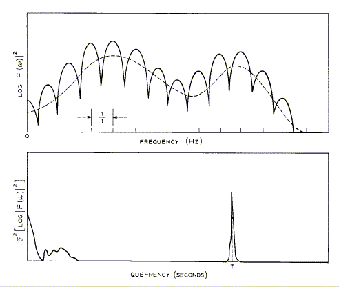
to consider first the spectral representation that we have in figure 4.7a,
a standard power spectral density function displayed on a logarithmic scale.

Figure 4.7. (a) Spectrum of a voiced speech segment; (b) the cepstrum of
(a). Reproduced from Noll (1967).
Ignore for a moment the fact that the horizontal axis of figure 4.7
(a) is a frequency scale; after all, that is just a label that we give to
the graph. Suppose that the graph we are looking at here were a short segment
of a signal in the time domain, a short time-varying signal. We want to find
the distance between the smaller peaks, and, second, the distance between
the larger peaks. In the time domain that would amount to determining the
frequency of the smaller vibrations and the frequency of the larger vibrations.
If this were a time domain signal we could do a Fourier analysis of it, and
that would tell us the frequency of the higher frequency events (the little
peaks) as well as the lower frequency events (the big peaks). In terms of
what we know this graph to represent, the higher frequency peaks represent
the harmonics and the slower frequency peaks represent the underlying resonances.
So if we were to take a Fourier analysis of this graph, that would give us
a technique for separating out the narrow harmonic peaks from the broad resonance
peaks. So, having applied the Fast Fourier Transform once, to get the power
spectrum, if we apply it again, a second time, we will be able to measure
the time interval between the little peaks and the time interval between
the big peaks. However since we are mapping not from the time domain to the
frequency domain on this second application, but from the frequency domain
back into the time domain, the operation that we use is not an FFT as such,
but an inverse Fast Fourier Transform. This will have the same separation
effect but will take us from the frequency domain back into the time domain.
What is this time domain that arises as the result of performing an inverse
Fast Fourier Transform to a log power spectral density? Well, it is called
quefrency, a term coined by Bogert et al. (1963) that is intended
to denote the inverse of frequency in some respect, the inverse of frequency
being a time domain unit. On the horizontal axis of figure 4.7b it is given
in seconds, though as we shall see the units of quefrency will turn out to
be samples of the original signal. The quefrency of the spike that
we see representing the fundamental frequency will turn out to be the period
(in samples) of the fundamental frequency of the original signal. You can
see in figure 4.7b the result of applying an inverse Fast Fourier Transform
to a log power spectrum. There is one sharply demarcated spike at around
T seconds on the scale, which is the spike representing the fundamental
frequency. If T = 8.4 ms, for instance, the frequency will be 119 Hz,
since f = 1/T. At the left-hand end of the horizontal axis,
that is quefrencies of events with a very much smaller period, we have peaks
which represent the resonances of the vocal tract. Note that there is a very
clear separation between the fundamental frequency and the resonances. That
is because the fundamental frequency, the period of the glottal wave may
be of the order of say 10 milliseconds, whereas the period -if that is the
right word to use - the time taken for each oscillation of the resonators
is very much shorter. At a sampling rate of 8000 samples a second, a resonance
at 4000 Hz, for instance, would have a period of just 2 samples, a quarter
of a millisecond.
Next: Computation of
the cepstrum in C

